SOPALE
Sopale Nested
Processing SOPALE Output
Printing
MOZART
TMM (Thermo-mechanical Model)
old SOPALE documentation
Geodynamics home page
|
SOPALE Boundary Condition Input
Description of input parameters for values of type_bc:
type_bc = 1
vleft vright xsleft xsright
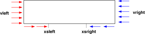 vleft
x (horizontal) velocity at left side boundary and left portion of bottom boundary
vright
x (horizontal) velocity at right side boundary and right portion of bottom boundary
xsleft
x position marking the left boundary of zone at the bottom where x velocity changes linearly from
vleft to vright
xsright
x position marking the right boundary of zone at the bottom where x velocity changes linearly
from vleft to vright
vleft
x (horizontal) velocity at left side boundary and left portion of bottom boundary
vright
x (horizontal) velocity at right side boundary and right portion of bottom boundary
xsleft
x position marking the left boundary of zone at the bottom where x velocity changes linearly from
vleft to vright
xsright
x position marking the right boundary of zone at the bottom where x velocity changes linearly
from vleft to vright This type of boundary condition does not allow vertical velocities on the
left or right boundaries; i.e. these are not roller boundaries.
Use this value of type_bc for models where the deformation does not
reach to the ends of the Eulerian mesh.
NOTE: this means there is no need to modify the Lagrangian
grid that is outside the Eulerian mesh owing to vertical
movements at the left and right boundaries.
For cases where the left and/or right boundaries move vertically,
use type_bc = 11.
Back to top
type_bc = 3
[2003/02/10] Use type_bc = 300 instead of type_bc = 3 if you
want to use this kind of boundary condition. Type_bc = 300 is
a corrected version of type_bc = 3.
vxleft_up vxleft_down yleft1 yleft2 rollleft
vxright_up vxright_down yright1 yright2 rollright
vytop0 vxbottom0
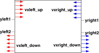 vxleft_up
x velocity at left boundary above yleft1
vxleft_down
x velocity at left boundary below yleft2
yleft1
vertical position at left boundary, above which
the x velocity is vxleft_up
yleft2
vertical position at left boundary, below which
the x velocity is yleft_down
vxleft_up
x velocity at left boundary above yleft1
vxleft_down
x velocity at left boundary below yleft2
yleft1
vertical position at left boundary, above which
the x velocity is vxleft_up
yleft2
vertical position at left boundary, below which
the x velocity is yleft_down
In the area between yleft1 and yleft2, the
x velocity makes a smooth transition between
vxleft_up and vxleft_down.
rollleft
= 1 means roller (free slip) boundary condition on
left boundary
= 0 means no vertical component to boundary condition
on left boundary, i.e. pinned (no slip)
vxright_up
x velocity at right boundary above yright1
vxright_down
x velocity at right boundary below yright2
In the area between yright1 and yright2, the x velocity makes a smooth transition between
vxright_up and vxright_down.
yright1
vertical position at right boundary, above which
the x velocity is vxright_up
yright2
vertical position at right boundary, below which
the x velocity is yright_down
rollright
= 1 means roller (free slip) boundary condition on
right boundary
= 0 means no vertical component to boundary condition
on right boundary, i.e. pinned (no slip)
vytop0
= 1 to set a rigid top (i.e. no vertical
velocities on top boundary)
= 0 vertical velocities allowed on top boundary
vxbottom0
= 1 for no slip on bottom (no horizontal
velocities on bottom)
= 0 horizontal velocites allowed on bottom
**** CAUTION ****
type_bc = 3 has special (likely inconsistent) properties when
used with roller side boundary conditions.
In the tectonic calculations all nodes on the side boundaries
above the base are rollers, therefore the surface nodes on
the sides can move vertically.
However, later when the surface is updated for tectonic
advection, the vertical advection of the surface nodes at
the sides is set to 0, thereby suppressing their advection
(inconsistent).
The advection of the surface nodes at the sides due to
surface processes is calcuated independently and depends on
the parameter nerode_ends.
Note that all other members of the type_bc=3 family allow
vertical advection of the surface nodes at the sides.
type_bc=3 was the original version and should only be used in
special circumstances.
[2003/02/10] Use type_bc = 300 instead of type_bc = 3 if you
want to use this kind of boundary condition. Type_bc = 300 is
a corrected version of type_bc = 3.
Back to top
type_bc = 4
type_bc = 4 is based on type_bc = 3, with 2 additional features:
- corrected behaviour for
side roller boundaries (the surface endpoints are allowed to move)
- the ability to restrict horizontal movement at the surface.
This means that with type_bc=4, we can totally restrict movement
at the surface (i.e. if vxtop0 = 1 and vytop0=1).
vxleft_up vxleft_down yleft1 yleft2 rollleft
vxright_up vxright_down yright1 yright2 rollright
vytop0 vxbottom0 vxtop0
vxleft_up
x velocity at left boundary above yleft1
vxleft_down
x velocity at left boundary below yleft2
yleft1
vertical position at left boundary, above which
the x velocity is vxleft_up
yleft2
vertical position at left boundary, below which
the x velocity is yleft_down
In the area between yleft1 and yleft2, the
x velocity makes a smooth transition between
vxleft_up and vxleft_down.
rollleft
= 1 means roller (free slip) boundary condition on
left boundary
= 0 means no vertical component to boundary condition
on left boundary, i.e. pinned (no slip)
vxright_up
x velocity at right boundary above yright1
vxright_down
x velocity at right boundary below yright2
In the area between yright1 and yright2, the x velocity makes a smooth transition between
vxright_up and vxright_down.
yright1
vertical position at right boundary, above which
the x velocity is vxright_up
yright2
vertical position at right boundary, below which
the x velocity is yright_down
rollright
= 1 means roller (free slip) boundary condition on
right boundary
= 0 means no vertical component to boundary condition
on right boundary, i.e. pinned (no slip)
vytop0
= 1 to set a rigid top (i.e. no vertical
velocities on top boundary)
= 0 vertical velocities allowed on top boundary
vxbottom0
= 1 for no slip on bottom (no horizontal
velocities on bottom)
= 0 horizontal velocites allowed on bottomvxtop0
1 = no horizontal velocities on top boundary
0 = horizontal velocities allowed on top boundary
CAUTIONVertical rolling at left and/or rigth boundaries will result in a verical mis-match between the Eulerian grid and the Lagrangian grid at the boundary. No correction is made to the Lagrangian grid for this effect. There is no known simple solution to this problem. User beware!
Back to top
type_bc = 10
This is the same as type_bc=1 with the addition of
sinusoidal noise to the x velocities at the bottom boundary between xsleft and xsright.
vleft vright xsleft xsright
ampnoise wavlnoise decaylnoise
vleft
x (horizontal) velocity at left side boundary and left portion of bottom boundary
vright
x (horizontal) velocity at right side boundary and right portion of bottom boundary
xsleft
x position marking the left boundary of zone at the bottom where x velocity changes linearly from
vleft to vright
xsright
x position marking the right boundary of zone at the bottom where x velocity changes linearly
from vleft to vrightampnoise
amplitude of sinusoidal noise as a velocity in SI units, m/s
wavlnoise
wavelength of sinusoidal noise in SI units, m
decaylnoise
length scale in SI units, m, over which the noise decays
to zero adjacent to xsleft and xsright
	 Choice of noise amplitude. For the noise velocity to give a
	 superimposed noise strain rate equal to alpha x mean velocity
	 gradient (where mean velocity = epsilon xx tectonic strain rate),
	 ampnoise should be set to:

             ampnoise = alpha x ( deltavx/ltrans)  x ( wavlnoise/4 )

         where deltavx = difference of velocity (m/s) across entire width of
                         transition zone (vxright-vxleft)
               ltrans = width (m) of transition zone (xsright-xsleft)
               wavelnoise = wavelength of the noise (m)
Back to top
type_bc = 11
vleft rollleft vright rollright xsleft xsright
vleft
x (horizontal) velocity at left side boundary and left portion of bottom boundary
vright
x (horizontal) velocity at right side boundary and right portion of bottom boundary
xsleft
x position marking the left boundary of zone at the bottom where x velocity changes linearly from
vleft to vright
xsright
x position marking the right boundary of zone at the bottom where x velocity changes linearly
from vleft to vright
rollleft
1 = allow left endpoint of surface to move vertically
0 = don't allow left endpoint of surface to move vertically
rollright
1 = allow right endpoint of surface to move vertically
0 = don't allow right endpoint of surface to move vertically
WARNING!
type_bc=11 allows vertical rolling of the
the left and right boundaries, except at the base.
No modification is made to the Lagrangian grid
outside the Eulerian domain. This means there will be
a mismatch between the Lagrangian and Eulerian meshes
at boundaries where rolling has occurred. This is
probably okay for cases where material is advected out
of the Eulerian domain. It is also okay for boundaries
where there is no advection into the domain. It is
up to the user to make sure this is satisfied.
Back to top
type_bc = 12
This is like type_bc=11, but allows x velocities to vary along
side boundaries (as type_bc 3 does).
vxleft_up vxleft_down yleft1 yleft2 rollleft
vxright_up vxright_down yright1 yright2 rollright
xsleft xsright
vxleft_up
x velocity at left boundary above yleft1
vxleft_down
x velocity at left boundary below yleft2
yleft1
vertical position at left boundary, above which
the x velocity is vxleft_up
yleft2
vertical position at left boundary, below which
the x velocity is yleft_down
In the area between yleft1 and yleft2, the
x velocity makes a smooth transition between
vxleft_up and vxleft_down.
rollleft
= 1 means roller (free slip) boundary condition on
left boundary
= 0 means no vertical component to boundary condition
on left boundary, i.e. pinned (no slip)
vxright_up
x velocity at right boundary above yright1
vxright_down
x velocity at right boundary below yright2
In the area between yright1 and yright2, the x velocity makes a smooth transition between
vxright_up and vxright_down.
yright1
vertical position at right boundary, above which
the x velocity is vxright_up
yright2
vertical position at right boundary, below which
the x velocity is yright_down
rollright
= 1 means roller (free slip) boundary condition on
right boundary
= 0 means no vertical component to boundary condition
on right boundary, i.e. pinned (no slip)

-
- xsleft
- x position marking the left boundary of zone at the bottom where x velocity changes linearly from vxleft_down to vxright_down
- xsright
- x position marking the right boundary of zone at the bottom where x velocity changes linearly from vxleft_down to vxright_down
WARNING!
type_bc=12 allows vertical rolling of the
the left and right boundaries, except at the base.
No modification is made to the Lagrangian grid
outside the Eulerian domain. This means there will be
a mismatch between the Lagrangian and Eulerian meshes
at boundaries where rolling has occurred. This is
probably okay for cases where material is advected out
of the Eulerian domain. It is also okay for boundaries
where there is no advection into the domain. It is
up to the user to make sure this is satisfied.
Back to top
type_bc = 30
type_bc = 30 is like type_bc=3, but with added sinusoidal noise
in the x velocity along the base.
vxleft_up vxleft_down yleft1 yleft2 rollleft
vxright_up vxright_down yright1 yright2 rollright
vytop0 vxbottom0 vybottom decaylvybottom
xvyleft xvyright
ampnoise wavlnoise decaylnoise xsleft xsright
vxleft_up
x velocity at left boundary above yleft1
vxleft_down
x velocity at left boundary below yleft2
yleft1
vertical position at left boundary, above which
the x velocity is vxleft_up
yleft2
vertical position at left boundary, below which
the x velocity is vxleft_down
In the area between yleft1 and yleft2, the
x velocity makes a smooth transition between
vxleft_up and vxleft_down.
rollleft
= 1 means roller (free slip) boundary condition on
left boundary
= 0 means no vertical component to boundary condition
on left boundary, i.e. pinned (no slip)
vxright_up
x velocity at right boundary above yright1
vxright_down
x velocity at right boundary below yright2
yright1
vertical position at right boundary, above which
the x velocity is vxright_up
yright2
vertical position at right boundary, below which
the x velocity is yright_down
In the area between yright1 and yright2, the x velocity makes a smooth transition between
vxright_up and vxright_down.
rollright
= 1 means roller (free slip) boundary condition on
right boundary
= 0 means no vertical component to boundary condition
on right boundary, i.e. pinned (no slip)
vytop0
= 1 to set a rigid top (i.e. no vertical
velocities on top boundary)
= 0 vertical velocities allowed on top boundary
vxbottom0
= 1 for no slip on bottom (no horizontal
velocities on bottom)
= 0 horizontal velocites allowed on bottom
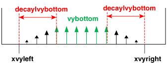 vybottom
maximum y (vertical) velocity for the bottom boundary between xvyleft
and xvyright
The bottom boundary y velocity is set to vybottom
between xvyleft and xvyright,
zero to the left of xvyleft,
and zero to the right of xvyright.
decaylvybottom
length to the right of xvyleft
and to the left of xvyright,
over which the bottom boundary y velocity decays linearly to zero.
xvyleft
Position on bottom boundary marking the left end of the section where bottom y velocity is nonzero.
xvyright
Position on bottom boundary marking the right end of the section where bottom y velocity is nonzero
ampnoise
amplitude of sinusoidal noise as a velocity in SI, m/s
wavlnoise
wavelength of sinusoidal noise in SI, m
decaylnoise
length scale in SI, m, over which the sinusoidal noise decays
to zero adjacent to xsleft and
xsright
xsleft
left limit in SI, m, for the added basal sinusoidal noise function
and for y velocity on bottom boundary
xsright
right limit in SI, m, for the added basal sinusoidal noise function
and for y velocity on bottom boundary
vybottom
maximum y (vertical) velocity for the bottom boundary between xvyleft
and xvyright
The bottom boundary y velocity is set to vybottom
between xvyleft and xvyright,
zero to the left of xvyleft,
and zero to the right of xvyright.
decaylvybottom
length to the right of xvyleft
and to the left of xvyright,
over which the bottom boundary y velocity decays linearly to zero.
xvyleft
Position on bottom boundary marking the left end of the section where bottom y velocity is nonzero.
xvyright
Position on bottom boundary marking the right end of the section where bottom y velocity is nonzero
ampnoise
amplitude of sinusoidal noise as a velocity in SI, m/s
wavlnoise
wavelength of sinusoidal noise in SI, m
decaylnoise
length scale in SI, m, over which the sinusoidal noise decays
to zero adjacent to xsleft and
xsright
xsleft
left limit in SI, m, for the added basal sinusoidal noise function
and for y velocity on bottom boundary
xsright
right limit in SI, m, for the added basal sinusoidal noise function
and for y velocity on bottom boundary
NOTE:
In the Lagrangian grid below the Eulerian grid (i.e. where
the y coordinate of the grid is less than 0), the
y velocities are set to the bottom boundary y velocity.
For now (as of June 4, 2002) we are setting the x
velocities in this part of the Lagrangian grid to zero.
This means that the mechanical and thermal materials in
in this area of the Lagrangian grid are advected
but not deformed.
Back to top
type_bc = 31
type_bc = 31 is like type_bc=3, but with added white noise
in the x velocity along the base.
vxleft_up vxleft_down yleft1 yleft2 rollleft
vxright_up vxright_down yright1 yright2 rollright
vytop0 vxbottom0
vybottom decaylvybottom xvyleft xvyright
ampnoise decaylnoise xsleft xsright
vxleft_up
x velocity at left boundary above yleft1
vxleft_down
x velocity at left boundary below yleft2
yleft1
vertical position at left boundary, above which the x velocity is vxleft_up
yleft2
vertical position at left boundary, below which the x velocity is yleft_down
In the area between yleft1 and yleft2, the x velocity makes a smooth transition between vxleft_up and vxleft_down.
rollleft
= 1 means roller (free slip) boundary condition on left boundary
= 0 means no vertical component to boundary condition on left boundary, i.e. pinned (no slip)
vxright_up
x velocity at right boundary above yright1
vxright_down
x velocity at right boundary below yright2
In the area between yright1 and yright2, the x velocity makes a smooth transition between vxright_up and vxright_down.
yright1
vertical position at right boundary, above which the x velocity is vxright_up
yright2
vertical position at right boundary, below which the x velocity is yright_down
rollright
= 1 means roller (free slip) boundary condition on right boundary
= 0 means no vertical component to boundary condition on right boundary, i.e. pinned (no slip)
vytop0
= 1 to set a rigid top (i.e. no vertical velocities on top boundary)
= 0 vertical velocities allowed on top boundary
vxbottom0
= 1 for no slip on bottom (no horizontal velocities on bottom)
= 0 horizontal velocites allowed on bottom
vybottom
maximum y (vertical) velocity for the bottom boundary between xvyleft and xvyright
The bottom boundary y velocity is set to vybottom between xvyleft and xvyright, zero to the left of xvyleft, and zero to the right of xvyright.
decaylvybottom
length to the right of xvyleft and to the left of xvyright, over which the bottom boundary y velocity decays linearly to zero.
xvyleft
Position on bottom boundary marking the left end of the section where bottom y velocity is nonzero.
xvyright
Position on bottom boundary marking the right end of the section where bottom y velocity is nonzero
ampnoise
maximum amplitude of white noise as a velocity in SI, m/s
decaylnoise
length scale in SI, m, over which the white noise decays
to zero adjacent to xsleft and xsright
xsleft
left limit in SI, m, for the added basal white noise function
and for y velocity on bottom boundary
xsright
right limit in SI, m, for the added basal white noise function
and for y velocity on bottom boundary
Back to top
type_bc = 32
type_bc = 32 is like type_bc = 3, but with added sinusoidal
noise in the x body force along the nodes in rows noisenodey1 to noisenodey2 (inclusive).
vxleft_up vxleft_down yleft1 yleft2 rollleft
vxright_up vxright_down yright1 yright2 rollright
vytop0 vxbottom0 vybottom decaylvybottom
vxyleft vxyright
ampnoise wavlnoise decaylnoise xsleft xsright
noisenodey1 noisenodey2
vxleft_up
x velocity at left boundary above yleft1
vxleft_down
x velocity at left boundary below yleft2
yleft1
vertical position at left boundary, above which the x velocity is vxleft_up
yleft2
vertical position at left boundary, below which the x velocity is yleft_down
In the area between yleft1 and yleft2, the x velocity makes a smooth transition between vxleft_up and vxleft_down.
rollleft
= 1 means roller (free slip) boundary condition on left boundary
= 0 means no vertical component to boundary condition on left boundary, i.e. pinned (no slip)
vxright_up
x velocity at right boundary above yright1
vxright_down
x velocity at right boundary below yright2
In the area between yright1 and yright2, the x velocity makes a smooth transition between vxright_up and vxright_down.
yright1
vertical position at right boundary, above which the x velocity is vxright_up
yright2
vertical position at right boundary, below which the x velocity is yright_down
rollright
= 1 means roller (free slip) boundary condition on right boundary
= 0 means no vertical component to boundary condition on right boundary, i.e. pinned (no slip)
vytop0
= 1 to set a rigid top (i.e. no vertical velocities on top boundary)
= 0 vertical velocities allowed on top boundary
vxbottom0
= 1 for no slip on bottom (no horizontal velocities on bottom)
= 0 horizontal velocites allowed on bottom
vybottom
maximum y (vertical) velocity for the bottom boundary between xvyleft and xvyright
The bottom boundary y velocity is set to vybottom between xvyleft and xvyright, zero to the left of xvyleft, and zero to the right of xvyright.
decaylvybottom
length to the right of xvyleft and to the left of xvyright, over which the bottom boundary y velocity decays linearly to zero.
xvyleft
Position on bottom boundary marking the left end of the section where bottom y velocity is nonzero.
xvyright
Position on bottom boundary marking the right end of the section where bottom y velocity is nonzero
ampnoise
amplitude of sinusoidal noise as a velocity in SI, m/s
wavlnoise
wavelength of sinusoidal noise in SI, m
decaylnoise
length scale in SI, m, over which the sinusoidal noise decays
to zero adjacent to xsleft and xsright
xsleft
left limit in SI, m, for the added sinusoidal noise function on
rows noisenodey1 to noisenodey2; also the left limit for the y velocity on bottom boundary
xsright
right limit in SI, m, for the added sinusoidal noise function on
rows noisenodey1 to noisenodey2; also the right limit for y velocity on bottom boundary
noisenodey1
top row number where sinusoidal noise is to be added to x body
force
noisenodey2
bottom row number where sinusoidal noise is to be added to x body
force
Back to top
type_bc = 33
type_bc = 33 is like type_bc = 3, but with added white
noise in the x body force along the nodes in rows noisenodey1 to noisenodey2 (inclusive).
vxleft_up vxleft_down yleft1 yleft2 rollleft
vxright_up vxright_down yright1 yright2 rollright
vytop0 vxbottom0 vybottom decaylvybottom
vxyleft vxyright
ampnoise decaylnoise xsleft xsright
noisenodey1 noisenodey2
vxleft_up
x velocity at left boundary above yleft1
vxleft_down
x velocity at left boundary below yleft2
yleft1
vertical position at left boundary, above which the x velocity is vxleft_up
yleft2
vertical position at left boundary, below which the x velocity is yleft_down
In the area between yleft1 and yleft2, the x velocity makes a smooth transition between vxleft_up and vxleft_down.
rollleft
= 1 means roller (free slip) boundary condition on left boundary
= 0 means no vertical component to boundary condition on left boundary, i.e. pinned (no slip)
vxright_up
x velocity at right boundary above yright1
vxright_down
x velocity at right boundary below yright2
In the area between yright1 and yright2, the x velocity makes a smooth transition between vxright_up and vxright_down.
yright1
vertical position at right boundary, above which the x velocity is vxright_up
yright2
vertical position at right boundary, below which the x velocity is yright_down
rollright
= 1 means roller (free slip) boundary condition on right boundary
= 0 means no vertical component to boundary condition on right boundary, i.e. pinned (no slip)
vytop0
= 1 to set a rigid top (i.e. no vertical velocities on top boundary)
= 0 vertical velocities allowed on top boundary
vxbottom0
= 1 for no slip on bottom (no horizontal velocities on bottom)
= 0 horizontal velocites allowed on bottom
vybottom
maximum y (vertical) velocity for the bottom boundary between xvyleft and xvyright
The bottom boundary y velocity is set to vybottom between xvyleft and xvyright, zero to the left of xvyleft, and zero to the right of xvyright.
decaylvybottom
length to the right of xvyleft and to the left of xvyright, over which the bottom boundary y velocity decays linearly to zero.
xvyleft
Position on bottom boundary marking the left end of the section where bottom y velocity is nonzero.
xvyright
Position on bottom boundary marking the right end of the section where bottom y velocity is nonzero
ampnoise
maximum amplitude of white noise as a velocity in SI, m/s
decaylnoise
length scale in SI, m, over which the white noise decays
to zero adjacent to xsleft and xsright
xsleft
left limit in SI, m, for the added white noise function on
rows noisenodey1 to noisenodey2;
also the left limit for y velocity on bottom boundary
xsright
right limit in SI, m, for the added noise function on
rows noisenodey1 to noisenodey2;
also the right limit for y velocity on bottom boundary
noisenodey1
top row number where white noise is to be added to x
body force
noisenodey2
bottom row number where white noise is to be added to x
body force
type_bc = 300
vxleft_up vxleft_down yleft1 yleft2 rollleft
vxright_up vxright_down yright1 yright2 rollright vytop0 vxbottom0
reference_pressure_column reference_material [ pump_time [ isos_time_scale [ delta_vel_factor ]]]
vxleft_up
x velocity at left boundary above yleft1
vxleft_down
x velocity at left boundary below yleft2
yleft1
vertical position at left boundary, above which the x velocity
is vxleft_up
yleft2
vertical position at left boundary, below which the x velocity
is yleft_down
In the area between yleft1 and
yleft2, the x velocity makes a
smooth transition between vxleft_up and vxleft_down.
rollleft
= 1 means roller (free slip) boundary condition on left
boundary
= 0 means no vertical component to boundary condition on left
boundary, i.e. pinned (no slip)
vxright_up
x velocity at right boundary above yright1
vxright_down
x velocity at right boundary below yright2
In the area between yright1
and yright2, the x velocity makes
a smooth transition between vxright_up and vxright_down.
yright1
vertical position at right boundary, above which the x
velocity is vxright_up
yright2
vertical position at right boundary, below which the x
velocity is yright_down
rollright
= 1 means roller (free slip) boundary condition on right
boundary
= 0 means no vertical component to boundary condition
on right boundary, i.e. pinned (no slip)
vytop0
= 1 to set a rigid top (i.e. no vertical velocities on top
boundary)
= 0 vertical velocities allowed on top boundary
vxbottom0
= 1 for no slip on bottom (no horizontal velocities on
bottom)
= 0 horizontal velocites allowed on bottom
reference_pressure_column
If this value is 0, then no pressure pumping is done.
If this value is positive, it is the number of elemental
column of Eulerian grid to use for the reference
pressure. Example: if the reference_pressure_column = 20, then
the lithostatic pressure at the base of the 20th (elemental)
column at timestep 1 is the pressure value that we will want to
maintain
If this value is negative, then it means that on a restart, we
will use its absolute value as the number of the elemental column
of the Eulerian grid to use for the reference pressure, and we
will calculate using the lithostatic pressures in the restart
file.
Normally, on a restart, we would use the reference
pressure saved in the restart file. However, if the restart file
was from a run without the pressure pump option, the reference
pressure would have been saved as 0; in this case we would want
to re-calculate a reference pressure.
If the pressure pump is ON, then
align_time should
be 1 on any restarts. (Since version 2009-07-26_22.9)
reference_material
material number for reference material The velocities will be
adjusted using the density of the reference material in the
calculation of pressure. [NOTE: for code from code-nov16-05-matsets+ and later, this
is the material "color" number, not the material set number.]
The parameters reference_pressure_column and reference_material were added with code-sep13-04-pump for the "pressure
pump" option. Pressure pumping maintains the pressure at the base
of the model by adjusting the vxleft_down and vxright_down to fine-tune the flow of
material in or out of the model. A value of delta_vel (delta velocity) is calculated
based on the density of the reference material, the reference
pressure we want to maintain, and the values of yleft2 and yright2. The delta_vel is then added to the values of
vxleft_down and vxright_down.
Since version 2009-07-26_21.2
pump_time
Length of time the pump will take to correct pressure
differences. For most uses this should be set to the mechanical
timestep length, dt, in which case the pump attempts to correct
pressure differences in one mechanical timestep.
Said another way: the time (in seconds) over which
delta_vel is calculated. Optional parameter.
pump-time is a special parameter only to be used with models
that have special initial conditions including an initial phase of
special isostatic equilibration. Standard models should use the
default dt. Users wanting to isostatically re-equilibrate models
and/or control bathtub oscillations should use the parameter
delta_vel_factor (see below)
Default is dt.
Since version 2009-07-26_21.3
Calculation of delta_vel changed:
- Before time = pump_time, normal start, to calculate delta_vel, use
- plithob average from the first call to pump_calculate_deltav
- pump_time
- Otherwise, to calculate delta_vel, use
- the current plithob average.
- dt
Since version 2009-07-26_22.9
Calculation of delta_vel changed: see the source
code in pressure_pump.f for details.
Since version 2009-07-26_23.0
isos_time_scale
scale factor, used in the calculation of delta_vel2.
It is the number of timesteps that isostatic
re-equilibration will take
isos_time_scale is a special parameter used in conjuction
with pump_time and is only to be used with models that have
special initial conditions including an initial phase of special
isostatic equilibration. Standard models should use the value
1.0d0
Default is 10.0
Since version 2009-07-26_29.0
delta_vel_factor
scale factor used to multiply delta_vel determined by the
pressure pump. The velocity correction to the boundary
conditions that is applied is
delta_vel_factor x delta_vel This means that only the
fraction delta_vel_factor of the velocity correction (delta_vel)
is applied at this time step.
For example delta_vel_factor = 0.1d0
will result in pressure corrections that are spread over
approximately 10 timesteps. Using the delta_vel_factor = 1.0 can
exacerbate 'bathtub oscillations' - violent swings in the model
velocities that alternate each timestep. These can be damped by
using values between 0.5d0 and 1.0d-2
Default is 1.0 up to version 2013-06-28_1.0
Default is 0.1 after version 2013-06-28_1.0
Back to top
type_bc = 301 (deprecated)
This version is deprecated.
(before version 2013-01-29_1.0)
Similar to type 300. In type 300, constant velocities are
applied to the top and bottom of each side of the model. The
velocities are supposed to be choosen so that the mass (or
volume, if density is assumed to be constant) in the model
remains constant.
In type 301
- In each time step, at the top of the mechanical loop,
before the iteration over velocity solutions starts, the
bottom velocities (vxleft_down, vxright_down) are
re-calculated (from vxleft_up, vxright_up, and geometry) to
values that conserve mass. Actually, the attempt is to
conserve volume. We want volume in = volume out.
- The distribution of volumes (into or out of) the bottom
is balanced as described under fraction_left.
- Then mantle_wind_vel is added to the bottom velocities.
- At the bottom the mechanical loop, in each time step,
after the velocity calculation has completed, the upper
velocities (vxleft_up, vx_right_up) are re-calculated so
that the velocities applied to the top left region and the
top_right region are scaled so that the corresponding forces
approximate target_force_left and target_force_right. The
scaling is described below .
Comparing to type 300:
- The parameter vxleft_down has been replaced by
target_force_left.
- The parameter vxright_down has been replaced by
target_force_right.
- Optional parameters have been added. See below for a
complete list.
The calculations use either the tectonic or total driving
forces depending on the value of use_tectonic_forces.
use_tectonic_forces = 1 , the forces
are the tectonic forces
use_tectonic_forces = 0 , the forces are
the total forces
tectonic horizontal driving force (force_tect) = total horizontal
driving force ( force_dyna) - mean stress (force_epress) see .out file
for values of force_tect, force_dyna and force_epress
This means that the user must also supply either a tectonic or
total driving force as the target_force. This can either be obtained
from the output of an exisiting sopale run of the same model or by
estimating the forces. Generally, the best choice is to run a spin-up
phase without setting target forces and then use the output from this
model to restart with target forces obtained from the .out file of the
spin-up.
The rescaling formula (for vxleft_up, vxright_up) is:
Vre = Vc (+)OR(-) dabs(Vc) * D * (dabs(ft - f) / (dabs(ft) + dabs (f)))
This formula is used for rescaling both left and right
boundary velocities. So there is Vre_right and Vre_left.
There are 2 versions of the formula. When sign =
sign_positive use version with + sign. When sign =
sign_negative use version with - sign.
D is user supplied damping factor with value between 0.05
and 0.3 (add to input)
Vre is the rescaled boundary velocity for the upper
(lithospheric part) of the model. It is the value to be used
in bc301 for the boundary velocity for this timestep
Vc is the 'current' value of the boundary velocity (the
value used for the previous timestep)
f is the tectonic boundary force from the last time step,
f_left and f_right It is calculated as a moving average of the
force_average_ts last timesteps, where
force_average_ts is user supplied ....good value
is 50.
ft_left and ft_right are the target tectonic boundary
forces specified by the user in input. They can be changed on
a restart but are constant during the model run.
The volume displaced by the upper velocities is calculated
by summing velocity * area. (Time is the same for upper
and lower velocities, and therefore left out.)
volume = velocity * area
mantle_wind_vel
mantle_wind_vel (in the usual SI units). This velocity
is added to the velocites in the lower region ....below the
lithosphere, after all of the other velocities have been set
using the rescaling velocity. Note that the addition of this
velocity is with the same sign on both sides....in one side,
out the other.
Default: 0.0
fraction_left
Determines how the bottom velocities are distributed
between the left and right sides of the model.
'separate': Each side will be balanced separately.
After vxleft_up is re-calculated, vxleft_down will be set so
that volume_in = volume_out on the left side. The right
side calculation will be similar.
<number>: The volume change due to the upper
velocities will be distributed (in the lower region) between
the left and right sides of the model.
- fraction_left * volume_change will go into, or out of,
the left side.
- (1 - fraction_left) * volume_change will go into, or out
of, the right side.
0.5 will give equal volumes on each side.
Default: 'separate'
delta_vel_toler
When the pressure pump calculates delta_vel, the
calculation includes subtracting plithob in the reference
column from the average plithob. If abs ((ref_plithob -
ave_plithob) - 1.0) < delta_vel_toler, the calculation is
skipped and delta_vel is set to zero.
Default: 0.0
use_tectonic_forces
use_tectonic_forces = 1 , the forces are the tectonic
forces
use_tectonic_forces = 0 , the forces are
the total forces
Default: 1
In each timestep after vxleft_up and vxright_up are
re-calculated they are compared to these minimum and
maximum velocities and set to one of these values if
'out of range'.
In version 2011-12-01_9.0
In version 2012-06-08_2.0
Since version 2012-06-08_2.0, an optional parameter:
Since version 2012-11-08_1.0 an optional parameter:
type_bc = 301
type 301: In each time step,
- At the top of the mechanical loop, before the iteration
over velocity solutions starts, the bottom velocities
(vxleft_down, vxright_down) are calculated (from
vxleft_up, vxright_up, and geometry) to values that conserve
mass. Actually, the attempt is to conserve volume. We want
volume in = volume out.
- The distribution of volumes (into or out of) the bottom
is balanced as descibed under
fraction_left.
- Then
mantle_wind_vel is added to the bottom
velocities.
- At the bottom the mechanical loop, after the velocity
calculation has completed, the upper velocities (vxleft_up,
vx_right_up) are re-calculated so that
target_force_left is applied to the top left
region, and target_force_right is applied to
the top right region.
version 2013-01-29_1.0 only
The rescaling formula (for vxleft_up, vxright_up) is:
Vre = Vc (+)OR(-) dabs(Vc) * D * (dabs(ft - f) / (dabs(ft) + dabs (f)))
Where
D is a user supplied damping factor. Suggested value between 0.05
and 0.3
mapping from equation variables to variables (others below)
| equation variable
| variable
|
| D
| vxleft_up_factor, vxright_up_factor
|
version 2013-02-08_2.0 (and later)
The rescaling formula (for vxleft_up, vxright_up) is:
Vre = Vc (+)OR(-) dabs(Vd) * (dabs(ft - f) / (dabs(ft) + dabs (f)))
Where
Vd is a user supplied velocity scale. Suggested value is
approximately 0.02 cm/yr (in metres/sec) meaning that it will
take at least 100 time steps to rescale the boundary velocity
by 2 cm/yr. Essentially, Vd sets a limit on the amount by
which the current velocity Vc can be changed each tmestep.
Vre is the rescaled boundary velocity for the upper
(lithospheric part) of the model. It will be used in the next
time step.
Vc is the current value of the upper boundary velocity
(the value used for the current timestep)
f is calculated from the boundary force, f_left and
f_right. The calculations use either
- tectonic, or
- total driving force
depending on the value of use_tectonic_forces. Once
the type (tectonic or total) of force has been selected, f is
calculated as either
- the raw boundary force from the current time step.
- the output of a low-pass time series filter, where the
time series is the boundary force of the previous
filter_length time steps.
filter_alpha sets the filter sensitivity.
ft (target_force_left and
target_force_right) are the target boundary forces
specified by the user. They can be changed on a restart but
are constant during the model run.
This formula is used for rescaling both left and right
boundary velocities. So there is Vre_right and Vre_left.
There are 2 versions of the formula.
- When sign = sign_positive use version with + sign.
- When sign = sign_negative use version with - sign.
C Left boundary use left boundary values of  Vc,  f and ft in formula
C -------------------------------------------------------------------
C Velocity is negative (outflux) and f is tensile  (+ve)
  if (Vc.le.0d0. and .f.ge.0d.0) then
C If (f > ft) decrease Vc (reduces f)
    if (f.ge.ft)  sign = sign_positive
    elseif  (f.le.ft) sign  = sign_negative

C Velocity is negative (outflux) and f is compressive (-ve)
  if (Vc.le.0d0. and .f.le.0d.0) then
C If (f > ft) increase Vc (reduces f)
    if (f.ge.ft)  sign = sign_positive
    elseif  (f.le.ft) sign  = sign_negative

C Velocity is positive (influx) and f is tensile (+ve)
  if (Vc.ge.0d0. and .f.ge.0d.0) then
C If (f > ft) increase Vc (reduces f)
    if (f.ge.ft)  sign = sign_positive
    elseif  (f.le.ft) sign  = sign_negative

C Velocity is positive (influx) and f is compressive (-ve)
  if (Vc.ge.0d0. and .f.le.0d.0) then
C If (f > ft) decrease Vc (reduces f)
    if (f.ge.ft)  sign = sign_positive
    elseif  (f.le.ft) sign  = sign_negative

C Right boundary use right boundary values of  Vc,  f and ft in formula
C ---------------------------------------------------------------------

C Velocity is negative (influx) and f is tensile  (+ve)
  if (Vc.le.0d0. and .f.ge.0d.0) then
C If (f > ft) increase Vc (reduces f)
    if (f.ge.ft)  sign = sign_negative
    elseif  (f.le.ft) sign  = sign_positive

C Velocity is negative (influx) and f is compressive (-ve)
  if (Vc.le.0d0. and .f.le.0d.0) then
C If (f > ft) decrease Vc (reduces f)
    if (f.ge.ft)  sign = sign_negative
    elseif  (f.le.ft) sign  = sign_positieve

C Velocity is positive (outflux) and f is tensile (+ve)
  if (Vc.ge.0d0. and .f.ge.0d.0) then
C If (f > ft) decrease Vc (reduces f)
    if (f.ge.ft)  sign = sign_negative
    elseif  (f.le.ft) sign  = sign_positive

C Velocity is positive (outflux) and f is compressive (-ve)
  if (Vc.ge.0d0. and .f.le.0d.0) then
C If (f > ft) increase Vc (reduces f)
    if (f.ge.ft)  sign = sign_negative
    elseif  (f.le.ft) sign  = sign_positive
This means that the user must also supply either a tectonic or
total driving force as the target_force. This can either be obtained
from the output of an exisiting sopale run of the same model or by
estimating the forces. Generally, the best choice is to run a spin-up
phase without setting target forces and then use the output from this
model to restart with target forces obtained from the .out file of the
spin-up.
The volume displaced by the upper velocities is calculated
by summing velocity * area. (Time is the same for upper
and lower velocities, and therefore left out.)
volume = velocity * area
type_bc = 312
type_bc = 312 is like type_bc = 3, but with added white noise
in the y velocity along the base.
vxleft_up vxleft_down yleft1 yleft2 rollleft
vxright_up vxright_down yright1 yright2 rollright
vytop0 vxbottom0
vybottom decaylvybottom xvyleft xvyright
ampnoise decaylnoise xsleft xsright
vxleft_up
x velocity at left boundary above yleft1
vxleft_down
x velocity at left boundary below yleft2
yleft1
vertical position at left boundary, above which the x velocity is vxleft_up
yleft2
vertical position at left boundary, below which the x velocity is yleft_down
In the area between yleft1 and yleft2, the x velocity makes a smooth transition between vxleft_up and vxleft_down.
rollleft
= 1 means roller (free slip) boundary condition on left boundary
= 0 means no vertical component to boundary condition on left boundary, i.e. pinned (no slip)
vxright_up
x velocity at right boundary above yright1
vxright_down
x velocity at right boundary below yright2
In the area between yright1 and yright2, the x velocity makes a smooth transition between vxright_up and vxright_down.
yright1
vertical position at right boundary, above which the x velocity is vxright_up
yright2
vertical position at right boundary, below which the x velocity is yright_down
rollright
= 1 means roller (free slip) boundary condition on right boundary
= 0 means no vertical component to boundary condition on right boundary, i.e. pinned (no slip)
vytop0
= 1 to set a rigid top (i.e. no vertical velocities on top boundary)
= 0 vertical velocities allowed on top boundary
vxbottom0
= 1 for no slip on bottom (no horizontal velocities on bottom)
= 0 horizontal velocites allowed on bottom
vybottom
maximum y (vertical) velocity for the bottom boundary between xvyleft and xvyright
The bottom boundary y velocity is set to vybottom between xvyleft and xvyright, zero to the left of xvyleft, and zero to the right of xvyright.
decaylvybottom
length to the right of xvyleft and to the left of xvyright, over which the bottom boundary y velocity decays linearly to zero.
xvyleft
Position on bottom boundary marking the left end of the section where bottom y velocity is nonzero.
xvyright
Position on bottom boundary marking the right end of the section where bottom y velocity is nonzero
ampnoise
amplitude of white noise as a velocity in SI, m/s
decaylnoise
length scale in SI, m, over which the white noise decays
to zero adjacent to xsleft and xsright
xsleft
left limit in SI, m, for the added basal white noise function
and for y velocity on bottom boundary
xsright
right limit in SI, m, for the added basal white noise function
and for y velocity on bottom boundary
Back to top
This page was last modified on Thursday, 01-Aug-2013 13:59:33 ADT
Comments to geodynam at dal dot ca
|